
Features
- Effectively controls many drive by wire throttle valves
- Fast response & precise operation
- CAN bus enabled
- 0-5V Idle control
- Antilag function
- Compatible with all standalone ECUs
- Fully safe and secure
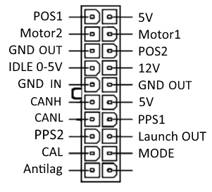
Pinout
How to install
Connection to the throttle valve
Every Electronic throttle valve has 6 important signals and they need to be connected to the top 6 pins of the DBW controller above.
2 of them are driving the motor inside the valve. They are marked as Motor1 and Motor2 on the pinout above. These can be easily discovered at the throttle connector by checking for low resistance <10ohm between the pins. Polarity is not important.
There are two position sensors inside the electronic throttle and they go to POS1 and POS2. It doesn’t matter which one is 1 and which is 2. The controller will detect them during calibration.
5V supply and ground for the position sensors. The throttle controller provides 5V and ground which are needed for the position sensors to work.
Power supply
Stable 12V and ground connections need to be connected to the corresponding pins in the controller. 12V must be enabled when ignition is on. Ground wire is connected to the GND IN terminal.
Pedal Position sensors
The pedal position sensors work in the same way as the throttle position sensors. They need 5V and ground from the controller and provide PPS1 and PPS2 position signals. It is important that the PPS1 signal increases when pressing the pedal!
If PPS2 is not connected, the system will still work but with reduced reliability. If the only pedal position sensor (PPS1) is faulty or a wire gets disconnected the throttle valve could open. The Throttle controller will check for this second pedal position sensor during first calibration and use it if available.
Calibration
Connect the calibration wire (CAL) to ground before first use to calibrate the controller.
When first connected the controller should be calibrated so it knows the min, max positions of the throttle pedal and valve. It is important that the unit is calibrated before first use or when changing the throttle valve.
- Connect CAL wire to ground.
- Fully depress the throttle pedal and turn ignition ON. (Do not start the engine!)
- Fully release the throttle pedal.
- The throttle valve will move and find its limits. Wait 5 seconds and verify correct operation of throttle.
- Turn off ignition and disconnect CAL wire.
IDLE control
IDLE0-5V is an analogue input which can be used to control the idle speed of the engine. 5V is lowest idle, 0V (gnd) is highest idle. It can be connected to a standalone ecu pwm idle output.
Antilag mode
When activated it works by keeping the throttle valve open and enabling external launch control/ rev limiter when the pedal is released.
To set this up connect the “Mode” wire to ground. In order to actually activate it connect the “Antilag” wire to ground. When the pedal is released the throttle valve will go to a set position and the “Launch OUT” pin will be activated by outputting ground. To configure the valve antilag position and other options check the user manual.
CAN BUS connection to MS3 ECU
The LDperformance DBW module CAN connection works best when connected to MS3 ecu with firmware 1.5.2 and above. This allows full control of the throttle through the ECU including idle. Simply connect the CANH and CANL wires using two wires twisted together.
This is not a required step, the Throttle controller can work independently.
TunerStudio settings for DBW:
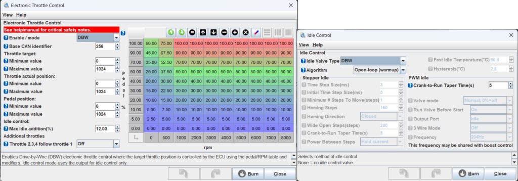
You might want to optimise the min and max values by looking at the gauges from “Throttle Test mode” from the CAN bus menu.
Compatibility
The DBW controller is tested to work very well with the following throttle valves:
- VAG 6 pin used on 1.8T and also VR6
- BMW
- Subaru impreza
- Lexus is200
- Mercedes V8
Safety
When both pedal position sensors are connected to the controller the system is guaranteed to never open the throttle valve without user request. An FMEA analysis proves that this is true if any component fails or any wire gets disconnected or shorted.
The controller is continuously monitoring both throttle position inputs and if there is sufficient difference between the two, it will stop operation and log an error code. Same applies for the pedal position sensors. Additionally the controller will halt and log an error if the throttle is open more than requested for a time period of >1s.
Safety checks are also performed on every power on. These include short circuit and open circuit detection on all mosfets and throttle motor open circuit.
When using the Antilag feature both “Antilag” and “mode” wires need to be connected to ground for the throttle to actually open. This is done to make sure it is not activated if one wire accidentally touches ground.


Reviews
There are no reviews yet.